Motor Driven Two-way Valve
manufacturer: Shanghai MeiYan Yi Pump & Valve Co., Ltd.
Eml: sales@1bengfa.com
Tel: +86 (21) 5640 2009
Mob: +86 138 1691 3072(WeChat Same Account)
product drawing
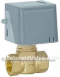
Motor driven two-way valve magnetic valves
summary
This electric valves are exclusively central air conditioning fan coil products by drive and body, two parts by a synchronous motors, drives, spring reset drive and manual control valve lever open. Body part adopts piston structure. Motorized valve can be used with temperature, the temperature control valves, electric valves motor open or close, cold and hot water piping of, or by fan coil air temperature, in order to realize the automatic adjustment.
Application scope and product features:
1 for cold and hot water control air conditioning system, piping open or close to control the temperature
2 drive from single hysteresis synchronous motor drive, the valve, the valve spring reset when not working in closed form, when need to work, the thermostat opens signals to provide a motorized valve on the ac power and action
3.. Open valve, frozen water or hot water into the fan-coil unit, provide for the room temperature, air conditioning and heating thermostat setting when to make electric valves, thermostat, reposition spring valve closes, thus truncation into the fan-coil unit, water valve closed and opened by temperature, temperature remains in the set temperature range.
4.. ZYFT series of electric valves and valve actuator adopts screw thread connection, but when valves are installed, then install drives. Field assembly, flexible, convenient connection. Drive to the graphic design can be installed, take up the space is little metope, reliable and durable products, low noise, can be in concealment type fan coil unit commonly wet high temperature environment.
technical parameter
| product introduction | SFD series motor-driven valve | SFD1 series motor-driven valve |
| material | brass body,stainless steel seat,Al shell | brass body,core,seal butterfly,stainless steel rod, spring |
| (Mpa) | 2.5MPa | |
| body connecting | standard cylinder pipe thread | |
| aplicable medium | freeze water, hot water or low pressure steam | |
| apllicable liquid temperature | 2℃-105℃ | |
| environment temperature and humidity | 0℃-50℃uncondensed | |
| stream control model | switch | |
| driven power supply | AC220V(+10%.15%),50Hzpower≤5W | |
| motor sort | hysteresis synchronism motor,rotate speed500r/min | |
| all journey time | open6sec.,close4sec. | open8sec.,close5 sec. |
drive specification type and technical parameter
| type | rated voltage | power | drive type | acting time matched with SRV2000valve | net weight |
| SRA2100-220 | AC220V±10% | 7W | electricity drive towards electricity machine valve spring reset | all open time: 10sec.after power on close time:5 sec.after outage | 0.3Kg |
| SRA2100-110 | AC110V±10% | ||||
| SRA2100-24 | AC24V±10% |
copper valve specification type and technical parameter
| type | valve model | connecting thread | flow factor (KV) | close differential pressure (MPa) | working medium | fluid temperature | environment temperature | store temperature | bearing presure (MPa) |
| SRV2200-15 | normal close two-way valve | G1/2 | 1.5 | 0.25 | freeze/ hot water | 2~94℃ | 0~60℃ max. relative hunidity is uncondensation | -20~65℃ max. relative humidity is uncondensation | 2.5 |
| SRV2300-15 | branch three way valve | G1/2 | 1.5 | 0.25 | |||||
| SRV2200-20 | normal close two-way valve | G3/4 | 2.5 | 0.10 | |||||
| SRV2300-20 | branch three way valve | G3/4 | 2.5 | 0.10 | |||||
| SRV2200-25 | normal close two-way valve | G1 | 4.8 | 0.06 | |||||
| SRV2300-25 | branch three way valve | G1 | 4.8 | 0.06 |
installation dimensions
|
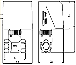
||||||||||||||||||||||||||||||||
| installation | ||
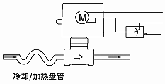
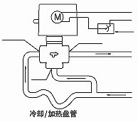
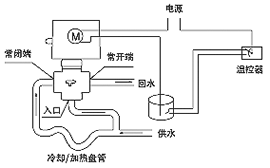
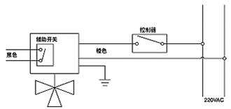
| Normal Closed two way valve and shunt three-way valve installation, as shown in figure 3, 4 and 5. For high-rise buildings, should be in bottom valve adopts tubes. Install valve, which should be paid attention to when the arrow in the body. If with complementary Switch, the wiring, as shown in figure 6 switch. | 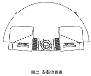 |
|
 |
 |
|
| two-way valve | three way valve | |
 |
 |
|
| (picyure 5) box-type switcher three-way valve | (picture6) assistant switch wiring scheme | |

